Architectural drawings (visual works)

Taxonomy

Code

Scope note(s)

  • Drawings of architecture and drawings for architectural projects, whether the project was executed or not. The term may also refer to any image in a two-dimensional medium that serves this same purpose, including prints and computer images.

Source note(s)

  • Art & Architecture Thesaurus.

Display note(s)

Hierarchical terms

Architectural drawings (visual works)

Equivalent terms

Architectural drawings (visual works)

Associated terms

Architectural drawings (visual works)

153 Archival description results for Architectural drawings (visual works)

153 results directly related Exclude narrower terms

Edward Colonna

  • CA CAC 15
  • Fonds

"Architectural Drawings"
Canadian Pacific Railway Company Terminal Station and General Office Vancouver B.C., n.d., 17 drawings
Canadian Pacific Railway Company Vancouver Hotel Alterations and Additions., n.d., 9 drawings
Canadian Pacific Railway Company Regina Station, n.d., 5 drawings

"Dessins architecturaux, s. d., 7 dessins." S'y retrouvent les plans, les élévations, les coupes et les détails de la Gare centrale de Vancouver et des bureaux généraux du Canadien Pacifique de même que les dessins de la gare de Régina, également réalisés pour le compte du Canadien Pacifique.

Colonna, Edward, 1862-1948

Durnford, Bolton, Chadwick and Ellwood

  • CA CAC 11.03
  • Fonds
  • 1955-1969

"Architectural Drawings, 1955-69, 219 drawings." Architectural drawings documenting eleven projects are found in the CAC. The majority of the drawings are designs for a residential dwelling for J. A. Laing on lie Bizard, PQ (1961-2); other Montreal projects represented in the archives include additions and alterations to the house of N. L. C. Mather in Westmount (1959-60), an addition to the Canadian Society for the Prevention of Cruelty to Animals building on Jean Talon (1962-64), alterations to St. George's Church and a number of alterations to the Sommer Building on Mayor Street (1955-69).
"Photograph, 1959-60." A photograph of a finished exterior of the Mather house in Westmount, with alterations and an addition, is found in the archive.
"Professional Papers, 1958-69, 13 cm." Correspondence, specifications, notes, and statements relating to five projects, including an addition and alterations to the Mather house, alterations to St. George's Church and alterations to the Sommer Building.

"Dessins architecturaux, 1955-1969, 219 dessins." La CAC réunit des dessins architecturaux reliés à onze projets. La plupart des dessins se rapportent à la résidence de J. A. Laing à l'île Bizard (Québec) (1961-1962); au nombre des autres projets montréalais représentés dans le fonds,
signalons les annexes et modifications à la maison de N. L. C. Mather à Westmount (1959-1960), une annexe à l'immeuble de la SPCA, rue Jean-Talon (1962-1964), des modifications apportées à l'église St. George ainsi que des modifications apportées à l'immeuble Sommer, rue Mayor (1955-1969).
"Photographies, 1959-1960." Une photographie de la finition extérieure de la maison Mather à Westmount, avec modifications et annexes.
"Documents professionnels, 1958-1969, 13 cm." De la correspondance, des cahiers des charges, des notes et des relevés se rapportant à cinq projets, notamment à une annexe et des modifications à la maison Mather, ainsi qu'à des modifications à l'église St. George et à l'immeuble Sommer.

Durnford, Bolton, Chadwick and Ellwood

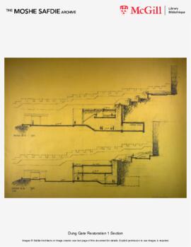
Dung Gate Restoration

  • CA CAC 58-1-10022
  • Subseries
  • between 1974 and 1985
  • Part of Moshe Safdie

The Dung Gate project represents Moshe Safdie's extensive work in the Jewish Quarter of Jerusalem's Old City. The gate, linking the old and the new cities of Jerusalem, was in urgent need of restoration to increase headroom and the construction of a "service" building adjacent to the wall intended to re-activate the area surrounding the gate. The site was steeply sloped and therefore the roof of the proposed structure was designed as a pedestrian pathway joining the existing Roman Cardo to a series of stepped landscaped terraces and a piazza on the roof of the service building.

Safdie Architects

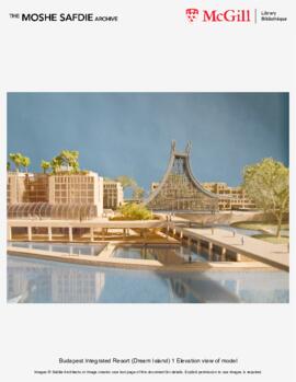
Dream Island Integrated Resort

The Dream Island Integrated Resort is located on Obudai Island on the Danube River in Budapest, Hungary. The project, totaling over 300,000 square meters, includes an entertainment district, a state-of-the-art casino and convention center, and hotels with over 3,000 rooms - all connected by an active marina and canal system. The project integrates new buildings with a network of existing historic buildings and the lush, natural landscape of Obudai Island.

The Island has two distinct halves, the east and the west, which are defined by the Great Bay and the marina. Visitors arrive at the north end of the Island and are introduced to the Resort by a Grand Fountain. From this location they can choose to circulate into either of the two halves of the Island. To the east is the hotel and casino complex and to the west lies the historic and entertainment district. The hotel complex consists of low, discrete buildings that are small in scale and organized along a man-made canal that is oriented north to south.

The hotel roofs accommodate amenities such as swimming pools, jogging paths and gardens. Running parallel to the canal, and below the level of the hotels, is the cardo - a main street of pedestrian activity with views to the Great Bay. Along the cardo guests have direct access to the marina level containing the casino, convention center, retail, restaurants, and waterfront amenities. To the west of the Great Bay a new museum, theater, and visitor's center are woven into the Roman archaeological site of Hadrian's Governors Palace.

Buildings in the historic and entertainment district, which once housed shipbuilding operations, are carefully preserved and converted to a mixed-use retail and entertainment complex. A pedestrian path, enclosed by a transparent glass ceiling, connects the 1600-seat performing arts theater, restaurants, outdoor caf?s, gardens, and a Film-Museum to the south. At the southernmost tip of the island a 112 meter tall elliptical wheel allows visitors to ascend and view the project, as well as survey the Danube River with the mainland of Buda to the west and Pest to the east.

Safdie Architects

Douglas Shadbolt

  • CA CAC 43
  • Fonds
  • 1959

"Architectural Drawings, 1959, 6 drawings." Included are drawings for proposed dormitory units for McGill University in Mount St. Hilaire, PQ.
"Photographs, 1959, 3 photographs." Proposed dormitory units for McGill University are documented by photographs.

"Dessins architecturaux, 1959, 6 dessins." Notamment les dessins d'une proposition de dortoirs pour l'Université McGill au Mont Saint-Hilaire (Québec). Ces dessins ont été dépouillés mais n'ont pas encore été décrits.
"Photographies, 1959, 3 photos." La proposition de dortoirs pour l'Université McGill est documentée par des photos. Celles-ci n'ont pas encore été décrites.

Shadbolt, Douglas, 1925-2002

D.J. Spence

  • CA CAC 81
  • Fonds
  • 1908-1970

Fonds consists of architectural drawings and related paper files, including:

-4 architectural plans (ink on linen) and 3 blueprints (working drawings) for L.E. Waterman Company Limited, Montreal, Quebec 1908, 1917, 1918, with 1 specification.

-Working drawings (elevations, plans, details, structural, electrical, mechanical) for Belgo Building, Montreal, Quebec 1912, 1913,1923, 1924, 1937, 1954, 1958, 1959, 1965, 1970 (10 paper, 30 linen, 14 blueprints).

-Architectural drawings, specifications and correspondence for the Seagrams Building, Montreal, Quebec 1929, 1931, 1955-57:
24 ink on linen
25 pencil on paper
8 pencil on waxed paper; 21 blueprints; 4 blueline prints; 4 reproductive print.
10 design drawings: floor plans, section.
5 development drawings structural plans, elevator hatchway, rear elevation, opening in party wall.
32 working drawings: floor plans, elevations, sections, roof plan mechanical plans.
23 shop drawings: schedule, footing plan, elevations, wiring, mezzanine, stairs, elevator elevator, penthouse, machinery, floor slab, metalwork, structural plans, steelwork, structural details, structural analysis of existing frame, structural steel plans.
23 details: front elevation, display window and shop entrance, revised elevation, stair framing, roof framing, existing party wall, front elevation including wall section and half plans lightwell, framing plan, flush duct, junction box, walker duct, office partitions, stairs, wall sections, vent dome, general office, windows, entrance doorway, stonework, piping, heating system, boiler room, interior elevations, panelling, display window.
1 sheet; Distillers Corporation Building History. July 5, 1974.
De Stein & McCutcheon. Analysis of Capacity of Existing Structural Frame to Support an Additional Story for Distillers Corporation Limited Peel Street Building. July 11,1955.
F.D. Mathias. Specifications for Heating, Plumbing and Ventilation. July 1955.
F. D. Mathias. Specification for Air conditioning. December 1955.
F. D. Mathias. Specifications for Additions and Alterations to 1430 Peel Street Distillers Corporation Limited. August 1, 1955.
F.D. Mathias. Specifications for Alterations to Heating System. June 1957.
Alterations to Heating System Addendum no.1. July 5, 1957.
Specification for Structural Steel.
Correspondence: De Stein & McCutcheon to F.D. Mathias, Montreal, August 8, 1956.
Correspondence: De Stein & McCutcheon to F.D. Mathias, Montreal, October 6, 1956.
F.D. Mathias. Work to be done for 3rd floor alteration. January 21, 1959.

-"Architectural drawings, specifications and soil investigation, Phillips Square Building, Montreal, Quebec 1947 - 1951."
18 pencil on trace, 5 ink on trace, 7 ink on linen, 5 blueline prints, 47 blueprints.
2 survey drawings: subdivision of lot, existing construction.
1 soil study: depth and nature of soil.
2 development drawings: wall section, electrical and boiler room layout.
37 working drawings: sections at main entrance doors, marble floor-main lobby and entrance, lobby and vestibule plan, vestibule showing marble, section through main entrance, main lobby new display windows, elevator pit, roof plan, seventh floor reflected ceiling plan, fourth floor reflected ceiling plan, first floor reflected ceiling plan, fifth floor reflected ceiling plan, second floor reflected ceiling plan, eleventh floor plan, ninth floor plan, eighth floor plan, basement floor plan, sixth floor plan, tenth floor plan, Phillips Square elevation, St. Catherine St. elevation, lane elevation, south elevation, cross section, basement plan, ground floor plan, first floor plan, typical plan, tenth floor plan, roof plan, drainage plan, heating riser, heating plan, lighting plan.
14 structural drawings: cooling tower base,pile cap, pile foundations, wall details, typical reinforced concrete details, caisson, plans: basement, ground floor, typical, tenth floor, roof, penthouse, foundation, awning boxes.
14 details: main stair, new store fronts south of main entrance, window, structural frame lobby partition, main entrance showing bronze and marble, set back for masonry work, lighting recess in lobby ceiling, corner entrance, storefronts revised, main stair, wall section, main entrance, electrical and boiler room layout.
6 shop drawings: riser diagram, location of ducts on fifth floor, eighth floor ductwork, sprinkler plans for basement, ground and first floors.
6 schedules: door, structural beam, structural slab, structural column.
Paper files: mechanical specifications, heating specifications, elevator specifications, specification of materials, soil investigation.

-"Architectural drawings and paper files, Insurance Exchange Building, Montreal, Quebec 1923, 1924, 1939."
45 ink on linen: 43 working drawings, 2 structural drawings.
20 pencil on paper: 20 working drawings.
62 blueprints: 2 surveys, 2 working drawings, 34 structural drawings, 9 electrical drawings, 9 mechanical drawings, 6 shop drawings.
Paper files: 3 specifications; Specification for Insurance Exchange Building, Specification for Plumbing, Heating and Ventilation 1923, Specification for Boilers, Brickwork and Breeching 1923.

-"Architectural drawings, Mansions Development Co. Limited, Montreal, Quebec 1924, 1925."
3 ink on linen: plan of levels of lot, property lines, block plan
4 pencil on paper: working drawings; rear elevations and exterior details.

Spence, D. J. (David Jerome), 1873-1955

David Robertson Brown and Hugh Vallance

  • CA CAC 10
  • Fonds
  • 1918

"Architectural Drawings, 1918, 21 drawings." Drawings of plans, elevations, and sections document the design of the Y.W.C.A. Building on Dorchester Blvd. (now Boul. René-Lévesque) and Stanley St. in Montreal.

"Dessins architecturaux, 1918, 21 dessins." Des dessins, des plans, des élévations et des coupes témoignent du projet de construction de l'immeuble du YWCA, boulevard Dorchester (maintenant boulevard René-Lévesque) à l'angle de la rue Stanley, à Montréal.

Brown, David Robertson, 1869-1946

Results 81 to 90 of 153